The skies were clear and the sun shone on the cold freezing morning of January 28, 1986. Kennedy Space Center in Florida was busy preparing the launch of the 25th space shuttle into space. Mission 51-L, the 10th flight of Orbiter Challenger. This was one of the most publicized launches because it was the first time that a civilian, a school teacher, was going into space. The launch of Challenger had been delayed five times due to bad weather, January 28 was the coldest day that NASA have ever launched a shuttle. The time had come, at 11:38 AM Eastern Standard Time, Challenger left Pad 39B at Kennedy. Seventy three seconds into flight, the Orbiter Challenger exploded, killing all seven of its crew. Challenger exploded 73 seconds after launch, but what actually happened at launch? What mechanically caused the explosion?
The temperature at ground level at Pad 39B was 36°F, that was 15°F cooler than any other previous launch by NASA. The Solid Rocket Boosters (SRB) was ignited, and the thundering noise started. At 0.68 seconds after ignition, videotape showed black smoke coming from the aft (bottom) field joint of the right SRB. The aft field joint is the lower portion of the SRB. The black smoke suggested that grease, joint insulation and rubber O-rings were being burned. The smoke continued to come from the aft field joint facing the Exterior Tank, on cycles of 3 puffs of smoke per second. The last puff of smoke was seen at 2.7 seconds. The black smoke was an indication that the aft field joint was not sealing correctly. Later in flight, flashes were seen on Challenger. Three bright flashes shot across the challenger’s wings, 45 seconds after lift off. Each of the three flashes lasted only 1/13 of a second. As these flashes had been seen on other shuttle missions and were not considered problems. Theses bright flashes were completely unrelated to the flame that was seen later in flight.
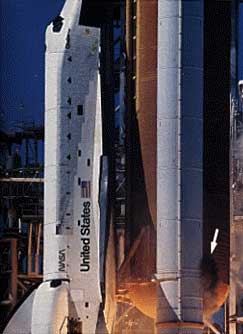
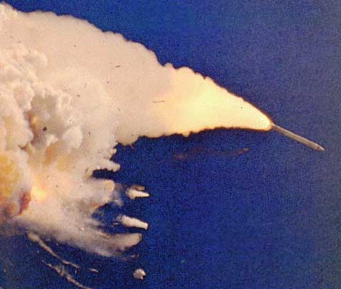
The first evidence of smoke
At 58.8 seconds into flight on enhanced film a flame was seen coming from the right SRB. The flame was coming from the aft center and aft joint, at 305° around the circumference of the SRB. The flame was burning gas that was escaping from the SRB. A fraction of a second later, at 59.3 seconds, the flame was well defined, and could be seen without enhanced film. As the flame increased in size, the flame had begun to push against the External Tank by the rushing air around the Orbiter. The SRB is attached to the External Tank by a series of struts along the side the External Tank. One of these struts is located at 310° of the circumference of the SRB. The flame as it grew pushed against this strut, with an intense heat of 5600°F, making it hot and weak.
The first sight that the flame was hitting the External Tank was at 64.7 seconds, when the color of the flame changed. Color change indicated that flame color was being produced by the mixing with another substance. This other substance was liquid Hydrogen which is stored in the External Tank. The External Tank stores Hydrogen and oxygen in two tanks. The top tank containing Oxygen and the bottom containing Hydrogen. Pressures changes from the Hydrogen tank confirmed there was leak. Forty-five milliseconds after the color change, a small glowing light developed between the External Tank and Challenger’s black tiles.
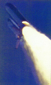
The glow of the flame from the SRB
From 72 seconds there was a very sudden chain of events that destroyed Challenger and the seven crew members on board. All of these events happened in less than two seconds. By now the lower strut, connecting the right SRB to the External Tank was extremely hot and very weak. With the amount of force given by the SRB, the lower strut broke away from both the right SRB and the External Tank. Allowing the right SRB to rotate freely around the top struts. The SRB was out of control, the bottom of the SRB swung around hitting, burning and denting Challengers wing. At 73.12 seconds into flight a white vapor was seen from the bottom corner of the right SRB. The External Tank was weak due to the intense heat given by the flame. The dome structure under the External Tank failed and fell. The tank of Hydrogen inside the External tank ruptured and released the liquid Hydrogen contents. With the sudden absence of Hydrogen, there was an extreme force that shot the Hydrogen tank forward into the Oxygen tank, that too burst.
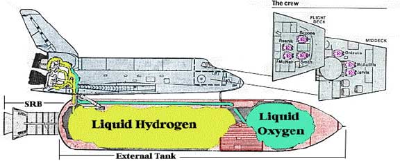
A diagram of the fuel tanks.
As the two intertanks collided, the top of the right SRB on the outside hit the top of the External Tank, and also broke the Oxygen tank. The white vapor seen was the mixture of Hydrogen and Oxygen. At 73.14 seconds, all the structures failed. Only milliseconds after the white vapor was seen from the right SRB, the glow had turned to a fireball in a huge explosion. The main explosion was the Hydrogen and Oxygen that come from the External Tank. Challenger was traveling at a speed of Mach 1.92, at a height of 46,000 feet, when it blow up. The last recorded transmission from Challenger was at 73.62 seconds after launch, when it truly fell apart.
Just before Challenger had blown up, it was engulfed in a cloud of smoke, that grew larger after the explosion. From under the gray smoke of the explosion, a red smoke was spreading. This red smoke was the reaction control system burning from the wreckage from Challenger. Debris from Challenger was seen falling and racing towards the ocean. Both of the SRBs flew in opposite directions out of the fireball and cloud. The explosives on the SRB were detonated by the United States Air Force Safety Commander, 110.25 seconds after launch. (36.6 seconds after the explosion.) The SRB have parachutes in the top cone so they can slowly come back to the ground in a normal launch. The parachutes from the blown SRB had come loose and were floating down to the ground. The watching public thought that the crew had escaped from the shuttle using their escape system. What the watches did not know was that there was no escape system on any of the shuttles. The SRB can be seen speeding away from the gulf of smoke caused by the exploding challenger.
Immediately after the explosion, the SRBs are flying away.
Root Cause Analysis
Aft Field Joint Failure
The right aft field joint sealing was the prime suspect to the cause of the accident, because the smoke after ignition and flame during flight, came from the region of the aft field joint.
The Solid Rocket Booster’s are made up of four main segments. They are joined together by a Tang and Clevis joint. Each segment has a Tang on the bottom and a Clevis at the top. The Clevis has a shape like a “U”, while the Tang has a shape of a straight line. The Tang would fit by sliding down the sides of the “U” of the Clevis. The Aft Mid Segment connects to the Aft Segment with the Nozzle. The joint that connects these two segments together is called the Aft Field joint. This is the joint that failed on the Right Solid Rocket Booster. The joint is sealed by two rubber O-rings, with a diameter of 0.280 inches (+ 0.005, -0.003). The sealing is used to stop the gases from inside the SRB escaping. The seal had failed, because the flame seen during the flight was gas being burnt.
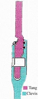
The Tang and Clevis joint.
Causes of Joint Seal Failure
There were a few causes that were found that could have lead to joint seal failure. These causes are:
- Assembly damage/Contamination — The joint seal could have been damaged or contaminated during assembly of the SRB.
- Gap opening — The gap between the joints open as the pressures are applied.
- O-ring compression — This depends on the width of the gap.
- Joint temperature — The temperature has effects on the sealing ability of the O-ring.
- Putty performance — Putty, Zinc chromate is applied before assembly inside the joint to stop gases going to the O-rings.
Assembly and Contamination
Assembly of the SRB could have damaged the sealing joint. The segments of the SRB are transported to the assembly plant horizontally. Each segment is heavy and therefore with its weight, changes the shape of the segment so it is not perfectly round. The irregular shape of the segments can be distorted and stressed from previous missions, and or the effects of handling. At assembly the aft segment is lowed vertically, with the tang sliding into the clevis of the previous joint. Because of the distortions, the dimensions of the segments may have changed. Mission 51-L, was one of the missions where the dimensions had changed. Even during the assembly process of the SRB the dimensions of segments continue to change, with the amount of weight that is applied to each of the segments. As stated, the shape and dimensions change, so at the assembly plant, to make the segments fit more easily the tang shape is changed with a special tool. The important thing during assembly is whether the diameters of both segments are the same. If the difference of diameters is too big, then the sides of both the tang and clevis are flat against each other. When this happens, the inside of the joint can not be seen to access if the joint is good. When the difference in diameters are small, then the tang is slanted against the clevis but, the slant still allows the assembly of the SRB to continue. Another thing that they look for during assembly is if the centers of the segments line up. A difference of +0.25 inches is allowed for mis-aligned segments. If the difference is more than +0.25 then there is a chance of contamination. When the tang and clevis fit together and the centers are off, then there is metal to metal contact. Metal splinters can flake off and can land on the O-ring. The metal segments can also scrape against the O-rings and ruin them. There has been tests that show that contaminates with a size of 0.001 and 0.003 inches in the joint have actually passed a leak test. Thus, there is always a possibility that contamination did actually occur on the SRB of mission 51-L.
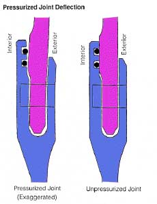
Gap Opening and Pressure Actuation
On the inside of the tang and clevis there is a gap that needs to be sealed. It is the O-rings that seal this gap. The size of the gap changes as the pressure of gases inside the SRB change. The gap gets bigger when the amount of pressure rises. Gap opening change is called Delta Gap Opening. There are two O-rings, the primary and secondary O-rings. The gap at each O-ring in the aft field joint is different, the gap at the primary O-ring is approximately 0.029 inches, and the secondary is approximately 0.017 inches. During launch the O-ring should move to seal the delta gap opening, and return to its proper state.
The gas pressure formed by combustion inside the SRB also helps to seal the O-ring. This process of sealing is called Pressure Actuation Of O-Ring Seal. As the gas goes toward the O-ring, gas meets one side of the O-ring and pushes the O-ring from all the sides possible into the gap, thus helping to seal the joint. The pressure is needed in the very early stages of SRB ignition. For pressure actuation of the O-ring to work perfectly, the gas pressure should be behind the O-ring while it is in its groove. The pressure can go around one complete side. When the gap is too big for the O-ring, then the gas will go past, blow by the O-ring and this would not seal the joint. Gas can blow by the O-ring when the groove that the O-ring sits in is too narrow. In this case the O-ring is squashed into the groove with all the O-ring sides flatly against the groove sides. The gas would not be able to help seal the joint. When blow by occurs the gas leaks, and the O-rings get damaged or even destroyed.
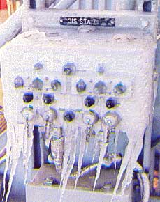
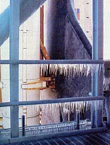
Temperature Effects
Temperature was also involved in failure of the joint seal. On the cold morning of the launch, the coldest joints were the aft field joints of the right SRB. The approximate temperature of the aft field joint on the right SRB was 28°± 5°F. The temperature of the opposite side, left SRB was approximately 50°F. There are two effects of O-rings at a low temperature. One effect of low temperature on O-rings is that they do not seal properly. When the O-rings are cold, they are very stiff and they do not move as quickly as they should. Tests were done to see how fast O-rings seal at different temperatures. At 75°F the O-rings seal within 530 milliseconds. On the opposite side of the scale an O-ring at 20°F takes 1.9 seconds to seal. It is this difference in time that could have put an end to Mission 51-L. From ten previous missions of shuttles, eight of these had O-ring damage in the SRB. The two missions that had no damage to the O-rings, were from warm launches. The joints of the SRBs had a temperature of 81°F and 79°F. This finding could be shown that temperature is a big contributor to the effects of O-ring damage. The second effect from cold temperature is ice formation. Ice can form in the joints, and damage the O-rings, which will lead to joint seal failure. Ice in the grooves for the O-rings would unseat them and would not let them seal the joint. Around Pad 39B there was plenty of evidence of ice formation. The entire tower was covered with icicles. Challenger, the SRBs and External Tank had been on the Pad for a total of 38 days. Within that there had been 7 inches of rain. There was a large chance that water had gone into the joints of the SRBs and damage some of the O-rings.
Putty Performance
Putty performance is another possible cause of the joint seal failure. Putty, Zinc chromate is placed on the inside of the joints before assembly. It is there to stop the heat of combustion gas from going to the O-rings. Putty is also forced between the gap of the tang and clevis, to make sure that the seal is tight. The Zinc chromate can affect the joint in many ways, one, putty can affect the amount of pressure that is sent to the O-ring for actuation of the O-ring. The hot gases can make holes in the putty, thus letting gas go through to the O-rings which could cause damage. Having gas go to the O-ring could decrease the time it takes for O-ring actuation. Second, the putty moves by gas pressure and could go all the way to the O-rings. The putty could be blown into the grooves of the O-rings and block the O-rings from properly sealing the joint.
SRB Shape Deformation During Launch
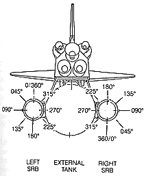
For most of the causes of the joint seal failure, it was assumed that the segments stay perfectly round during launch. When a shuttle is launched, the SRBs are actually subjected to a great deal of force. For the final launch of Challenger, the SRBs were bolted to the pad for 6.6 seconds after ignition. The great forces bend and strains the SRBs forward. The circular segments are changed to an elliptical shape. The side that is most flat of the elliptical is on the shortest distance between 045°-315° of the right SRB. The bending and straining occurs in cycles of three per second. At launch when the SRBs were ignited, there were puffs of smoke coming from the same location, also at three puffs per second. There are other changes with the forces being applied to the SRBs. The tang and clevis joints change shape and therefore the gap opening becomes bigger, thus the O-rings have a bigger gap to seal. If the O-ring does not follow the gap opening then the seal fails.
Conclusion
From the above information the cause for the explosion was the failure of the right SRB aft joint sealing, most likely due to the extremely cold temperature on the morning January 28, 1986. Out of the two SRBs that were used, the one that was in the extreme cold was the one that failed. O-rings when they are cold do not move as quickly as ones that are warm. Therefore if the O-rings were nearly frozen in place during ignition, the gases burnt the O-rings and produced the black smoke. Challenger left the launch pad and headed for space. During flight the O-rings continued to not seal the joint, and the gases leaked through the aft field joint. The flame grew larger and later blew Challenger up. January 28, 1986 was the day when seven US astronauts died when their shuttle exploded 73 seconds after launch. It was the coldest day in history that a shuttle has been launched. The cause of the accident was due to bad weather and the failure of the aft joint seal in the right Solid Rocket Booster. This tragic accident will always be remembered in the space program.